D. What is Class A, B, AB, ultralinear, etc?
1. Class A means that the power tube conducts the same amount of current all the time, whether idling or producing full power. Class A is very inefficient with electricity but usually gives very low distortion.
There are single-ended class-A, or SE, amplifiers. They use one or more tubes in parallel, which are all in phase with each other. This is commonly used in smaller guitar amps and in exotic high-end amplifiers. Many audiophiles prefer the SE amplifier, even though it has relatively high levels of even-order distortion. Most 300B high-end amplifiers are SE. Negative feedback, which can be used to decrease the distortion of an amplifier, is felt by some people to sound inferior. Most SE amps have no feedback.
Push-pull class-A amplifiers also exist--they use two, four or more tubes (always in pairs) which are driven in opposite phase to each other. This cancels out the even-order distortion and gives very clean sound. An example of a class-A push-pull amplifier is the Vox AC-30 guitar amp. Push-pull Class A operation usually involves low plate voltages and high plate currents, compared to Class AB operation below. The high currents might tend to wear out the tube cathodes faster than in an AB amplifier.
There are two kinds of class-A operation, which can apply to single-ended or push-pull.
-Class A1 means that the grid voltage is always more negative than the cathode voltage. This gives the greatest possible linearity and is used with triodes such as the SV300B, and with audio beam tetrodes and pentodes.
-Class A2 means that the grid is driven MORE POSITIVE than the cathode for part or all of the waveform. This means the grid will draw current from the cathode and heat up. A2 is not often used with beam tetrodes, pentodes or triodes like the SV300B, especially in audio. Usually a class-A2 amplifier will use tubes with special rugged grids, such as the SV811 and SV572 series of triodes.
Class A2 also requires a special driver circuit, that can supply power to the grid.
2. Class AB applies only to push-pull amplifiers. It means that when one tube's grid is driven until its plate current cuts off (stops) completely, the other tube takes over and handles the power output. This gives greater efficiency than Class A. It also results in increased distortion, unless the amplifier is carefully designed and uses some negative feedback. There are class-AB1 and class-AB2 amplifiers; the differences are the same as were explained above--the tube's grids are not (AB1) or are (AB2) driven positive.
3. Class B applies only to push-pull amplifiers in audio; it SOMETIMES applies to RF power amplifiers with one tube. It is like Class AB, except that the tubes idle at or near zero current. This gives even greater efficiency than Class A or AB. It also results in increased distortion, unless the amplifier is carefully designed and uses some negative feedback. If careful design is not undertaken, the result may be crossover distortion, which appears at the midpoint of the output waveform and has very bad-sounding effects in audio. Most solid-state audio amplifiers use class B, because the transistors undergo less heat stress when idling.
4. Ultralinear operation was invented by David Hafler and Herbert Keroes in 1951. It uses only beam tetrodes or pentodes, and special taps on the output transformer. The taps connect to the screen grids of the tubes, causing the screens to be driven with part of the output signal. This lowers distortion considerably. It is usually seen only in hi-fi amplifiers that use power tubes such as the SV6L6GC, SV6550C, EL84 or EL34.
E. Why are different kinds of power supplies used in various tube amplifiers? Why do some use tube amplifiers? Why do some use tube rectifiers, while others use solid-state rectifiers, while still others have electronic regulation?
Tube rectifiers are still used in power supplies of some guitar amps, because the current a tube rectifier can produce varies somewhat with the load. It is quite different in response from a solid-state rectifier. Many audiophiles also prefer this classic design for much the same reasons. Also, inexpensive solid-state rectifiers can put "hash" into a power supply, because of their slow transient capability while charging and recharging a filter capacitor 50/60 times a second. Special high-speed silicon rectifiers are available at high cost. They are rarely used in products other than a few high-end amplifiers. Tube rectifiers have faster transient response than most solid-state rectifiers, also making them useful in some high-end designs.
Regulated DC plate power can be very helpful in a push-pull Class AB amplifier. Because the amp draws greatly different current when at idle and when delivering full power, a regulated supply "sags" less at full power, producing better transient response in the amplifier. It is expensive to regulate the high voltages in a tube amplifier, so it is done only in expensive top-line models. Class A amplifiers have less need for regulation since they draw nearly the same DC power at all times. It is dependent on the circuit design. The only way to see if you need an amplifier with a regulated supply is to listen to it and carefully compare it with similar amps with unregulated supplies. Regulation is almost never used in guitar amps, since the DC power "sag" causes some signal compression, which is considered part of the desired sound effect inherent to a guitar amp.
F. What are the advantages of an OTL amplifier over a conventional one with an output transformer? Should I get an OTL? What about its reliability issues?
OTL, or output-transformerless, amplifiers are special high-end products. Because it is expensive and difficult to wind an output transformer for a tube amplifier to achieve the best possible performance, some designers have chosen to eliminate the transformer altogether. Unfortunately, tubes have relatively high output impedances compared to transistors. So, tubes with large cathodes and high peak emission capability are used---in many push-pull pairs. A well-designed OTL is capable of the best audio performance available today. OTLs usually require more maintenance and greater care in use than transformer-coupled amps. In recent years, OTLs have gotten a bad reputation for unreliability. This was only a problem with some low-cost manufacturers, who have since gone out of business. A well-designed OTL can be just as reliable as a transformer-coupled amp.
G. There's all this talk about "parallel feed", "shunt feed", SRPP, "mu followers", and the like. Which should I use? What's the difference?
Parallel feed and shunt feed are the same technique. Basically, a choke is used to load the power tube (usually one, in SE mode), while the output transformer is coupled to the plate of the tube through a capacitor. So, the plate current of the tube does not flow through the output transformer. This can be a very expensive technique to implement, since the choke must be as carefully wound as the output transformer. It does offer a possible performance improvement. You should try to audition a parallel-feed high-end amp before buying it. This technique is considered too expensive for use in guitar amps.
SRPP circuits and mu-follower circuits are special designs which use a lower tube (for gain), and an upper tube which serves as the plate load for the lower tube. The upper tube also acts as both a cathode follower and as a constant-current source for the lower tube. If properly designed, either circuit can offer improved performance over an ordinary resistor-loaded tube stage. These circuits are used only in preamp stages and in the driver stages of power amps, usually SE types, in high-end audio. If you want to build your own, see Technical Bulletin 27 for a good-quality mu-follower circuit that can be used as a line stage preamp or a power-amp driver.
If you want to learn more of the technical details behind vacuum-tube electronic design, we recommend the following books.
We recommend two recently-published books on circuit design, which the novice can derive much information from:
THE BEGINNER'S GUIDE TO TUBE AUDIO DESIGN, by Bruce Rozenblit (ISBN 1-882580-13-3);
and PRINCIPLES OF POWER, by Kevin O'Connor (ISBN 0-9698-6081-1).
Classic textbooks on tube audio design which were recently reprinted are:
THE RADIO DESIGNER'S HANDBOOK, by Langford-Smith (ISBN 1-7506-3635-1);
FUNDAMENTALS OF RADIO-VALVE TECHNIQUE, by J. Deketh (ISBN 1-8825-8023-0); and PRINCIPLES OF ELECTRON TUBES by Herbert Reich (ISBN 1-882580-07-9).
These books are more advanced and are not recommended for the novice. They are available from Old Colony Sound Lab, Antique Electronic Supply or other book dealers.
-A web site with much technical information about vacuum tubes is http://cernan.ecn.purdue.edu/~busenitz/vac.html
-If you want to learn more about tube materials and processes, the American Institute of Physics currently publishes two classic books that are chock-full of advanced information: HANDBOOK OF MATERIALS AND TECHNIQUES FOR VACUUM DEVICES, by Walter Kohl (ISBN 1-56396-387-6); and HANDBOOK OF ELECTRON TUBE AND VACUUM TECHNIQUES, by Fred Rosebury (ISBN 1-56396-121-0).
All of the books are available from large book dealers and from some of our audio-tube Stocking Distributors.
Information from www.vacuumtubes.net
5/12/09
USING TUBES(Part II)
USING TUBES(Part I)
A. Bias
Bias is a negative voltage applied to a power tube's control grid, to set the amount of idle current the tube draws. It is important to bias a tube to stay within its rated dissipation. Otherwise, you DO NOT need to worry about small deviances from the manufacturer's recommendations. Many times we have customers asking us things like, "I replaced the tubes, the old tubes ran at 35 mA, the new ones run at 38 mA. I'm worried that I have to rebias the amp." This is NOT worth worrying about. Especially with guitar amps--they tend to run their tubes at idle conditions which are conservative. Some high-end audio amps run their power tubes quite hard--in that case, rebiasing is necessary. Many amps have no bias adjustments at all, and are designed so that you do not need to concern yourself with bias. This includes most Mesa-Boogie guitar amps, most amps using EL84s, and many single-ended triode hi-fi amps. See our Technical Bulletin #7 for more information on biasing guitar amps. We suggest that users consult with the equipment manufacturer, if possible.
B. When should I replace the tubes?
Practically speaking, you should only replace tubes in an audio amplifier when you start to notice changes in the sound quality. Usually the tone will become "dull", and transients will seem to be blunted. Also, the gain of the amplifier will decrease noticeably. This is usually enough of a warning for tube replacement. If the user has very stringent requirements for observing tube weakening, the best way to check tubes is with a proper mutual- conductance-style tube tester. These are still available on the used market; though new ones have not been manufactured in many years. One tester is being manufactured today, the Maxi-Matcher. It is suitable for testing 6L6, EL34, 6550 and EL84 types. If you cannot get your own tube tester, speak to a service technician for his recommendations. See our cathode section 2A above for some idea of typical lifetimes for tubes.
Large ceramic power tubes are usually operated in equipment that has metering of the plate current or power output. When the tube cannot reach the rated plate current or power output for the equipment, the tube is usually considered to be at the end of its normal life. The operating manual should give a more complete procedure for estimating the health of the tube.
C. Blue Glow -- what causes it?
Glass tubes have visible glow inside them. Most audio types use oxide-coated cathodes, which glow a cheery warm orange color. And thoriated-filament tubes, such as the SV811 and SV572 triodes, show both a white-hot glow from their filaments and (in some amplifiers) a slight orange glow from their plates. All of these are normal effects. Some newcomers to the tube-audio world have also noticed that some of their tubes emit a bluish-colored glow. There are TWO causes for this glow in audio power tubes; one of them is normal and harmless, the other occurs only in a bad audio tube.
1) Most Svetlana glass power tubes show FLUORESCENCE GLOW. This is a very deep blue color. It can appear wherever the electrons from the cathode can strike a solid object. It is caused by minor impurities, such as cobalt, in the object. The fast-moving electrons strike the impurity molecules, excite them, and produce photons of light of a characteristic color. This is usually observed on the interior of the plate, on the surface of the mica spacers, or on the inside of the glass envelope. THIS GLOW IS HARMLESS. It is normal and does not indicate a tube failure. Enjoy it. Many people feel it improves the appearance of the tube while in operation.
2) Occasionally a tube will develop a small leak. When air gets into the tube, AND when the high plate voltage is applied, the air molecules can ionize. The glow of ionized air is quite different from the fluorescence glow above--ionized air is a strong purple color, almost pink. This color usually appears INSIDE the plate of the tube (though not always). It does not cling to surfaces, like fluorescence, but appears in the spaces BETWEEN elements. A tube showing this glow should be replaced right away, since the gas can cause the plate current to run away and (possibly) damage the amplifier.
PLEASE NOTE: some older hi-fi and guitar amplifiers, and a very few modern amplifiers, use special tubes that DEPEND on ionized gas for their normal operation.
-Some amps use mercury vapor rectifiers, such as types 83, 816, 866 or 872. These tubes glow a strong blue-purple color in normal use. They turn AC power into DC to run the other tubes.
-And occasionally, vintage and modern amplifiers use gas-discharge regulator tubes, such as types 0A2, 0B2, 0C2, 0A3, 0B3, 0C3 or 0D3.
These tubes rely on ionized gas to control a voltage tightly, and normally glow either blue-purple or pink when in normal operation. If you are unsure if these special tubes are used in your amplifier, consult with an experienced technican before replacing them.
ALSO NOTE: these light sources cannot be seen in metal-ceramic tubes, because their parts are opaque. As we said above, it is difficult to tell if a ceramic tube has become gassy. Usually, in a large radio transmitter, a gassy tube will arc over internally. (This does not damage the transmitter. It has protective circuits.) The equipment operating manual should give more information on this.
Information from www.vacuumtubes.net
WHY ARE TUBES STILL USED?
A. High-power RF applications
Many big radio stations continue to use big power tubes, especially for power levels above 10,000 watts and for frequencies above 50 MHz. High-power UHF TV stations and large FM broadcast stations are almost exclusively powered by tubes. The reason is cost and efficiency--only at low frequencies are transistors more efficient and less expensive than tubes.
Making a big solid-state transmitter requires wiring hundreds or thousands of power transistors in parallel in groups of 4 or 5 at a time, then mixing their power outputs together in a cascade of combiner transformers. Plus, they require large heat-sinks to keep them cool. An equivalent tube transmitter can use only one tube, requires no combiner (which wastes some power), and can be cooled with forced air or water, thus making it smaller than the solid-state transmitter.
This equation becomes even more pronounced at microwave frequencies. Nearly all commercial communication satellites use a traveling-wave tube for their "downlink" power amplifiers. The "uplink" ground stations also use TWTs. And for high power outputs, the tube seems to reign unchallenged. Exotic transistors still are used only for small-signal amplification and for power outputs of less than 40 watts, even after considerable advances in the technology. The low cost of RF power generated by tubes has kept them economically viable, in the face of advancing science.
B. Guitar amps
In general, only very low-cost guitar amplifiers (and a few specialized professional models) are predominantly solid-state. We have estimated that at least 80% of the market for high-ticket guitar amps insists on all-tube or hybrid models. Especially popular with serious professional musicians are modern versions of classic Fender, Marshall and Vox models from the 1950s and 1960s. This business is thought to represent at least $100 million worldwide as of 1997.
Why tube amplifiers? It's the tone that musicians want. The amplifier and speaker become part of the musical instrument. The peculiar distortion and speaker-damping characteristics of a beam-tetrode or pentode amp, with an output transformer to match the speaker load, is unique and difficult to simulate with solid-state devices, unless very complex topologies or a digital signal processor are used. These methods apparently have not been successful; professional guitarists keep returning to tube amplifiers.
Even the wildest rock musicians seem to be very conservative about the actual equipment they use to make their music. And their preferences keep specifying the proven technology of vacuum tubes.
C. Professional audio
The recording studio is somewhat influenced by the prevalence of tube guitar amps in the hands of musicians. Also, classic condenser microphones, microphone preamplifiers, limiters, equalizers and other devices have become valuable collectibles, as various recording engineers discover the value of tube equipment in obtaining special sound effects. The result has been huge growth in the sales and advertising of tube- equipped audio processors for recording use. Although still a minor movement within the multi-billion-dollar recording industry, tubed recording-studio equipment probably enjoys double-digit sales growth today.
D. High-end audio
At its low point in the early 1970s, the sales of tube hi-fi equipment were barely detectable against the bulk of the consumer-electronics boom. Yet even in spite of the closure of American and European tube factories thereafter, since 1985 the sales of "high-end" audio components have boomed. And right along with them have boomed the sales of vacuum-tube audio equipment for home use. The use of tubes in this regime has been very controversial in engineering circles, yet the demand for tube hi-fi equipment continues to grow.
E. For more information
See my cover article about the growth of modern tube audio, in the August 1998 issue of IEEE SPECTRUM magazine. It is available online at http://www.spectrum.ieee.org/select/0898/tube.html, and will shortly be available on the Svetlana website as technical bulletin number 39. For more information about why tubes are still used in high-power and high-frequency RF applications, see the article by Robert Symons in the April 1998 issue of IEEE SPECTRUM, page 52.
Information from www.vacuumtubes.net
3/19/08
Metal-ceramic power grid types
If you want to control a LOT of power, a fragile glass tube is more difficult to use. So, really big tubes today are made entirely of ceramic insulators and metal electrodes. Otherwise, they are much the same inside as small glass tubes--a hot cathode, a grid or grids, and a plate, with a vacuum in-between.
In these big tubes, the plate is also part of the tube's outer envelope. Since the plate carries the full tube current and has to dissipate a lot of heat, it is made with either a heat radiator through which lots of cooling air is blown, or it has a jacket through which water or some other liquid is pumped to cool it. The air-cooled tubes are often used in radio transmitters, while the liquid-cooled tubes are used to make radio energy for heating things in heavy industrial equipment. Such tubes are used as "RF induction heaters", to make all kinds of products--even other tubes.
Ceramic tubes are made with different equipment than glass tubes, although the processes are similar. The exhaust tubing is soft metal rather than glass, and it is usually swaged shut with a hydraulic press. All the equipment for exhausting and conditioning the tube is much larger, since there is more volume to exhaust, and the large metal parts require more aggressive induction heating. The ceramic parts are usually ring-shaped and have metal seals brazed to their edges; these are attached to their mating metal parts by welding or brazing.
By Eric Barbour
Information from www.vacuumtubes.net
Assembling the tube
A typical glass audio tube is made on an assembly line by people wielding tweezers and small electric spot-welders. They assemble the plate, cathode, grids and other parts inside a set of mica or ceramic spacers, then crimp the whole assembly together. The electrical connections are then spot-welded to the tube's base wiring. This work has to be done in fairly clean conditions, although not as extreme as the "clean rooms" used to make semiconductors. Smocks and caps are worn, and each workstation is equipped with a constant source of filtered airflow to keep dust away from the tube parts.
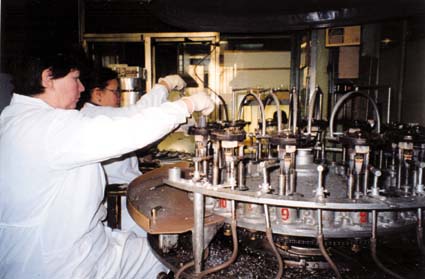
Once the finished assembly is attached to the base, the glass envelope can be slid over the assembly and flame-sealed to the base disc. A small glass exhaust tube is still attached, and enters the envelope. The tube assembly is attached to a processing machine (sometimes called a "sealex" machine, an old American brandname for this kind of device). The exhaust tubing goes to a multistage high-vacuum pump. The sealex has a rotating turntable with several tubes, all undergoing a different step in the process. (See more pictures of glass tube assembly and production)
First comes vacuum pumping; while the pump runs, an RF induction coil is placed over the tube assembly and all the metal parts are heated. This helps remove stray gases trapped in the parts, and also activates the cathode coating.
After 30 minutes or more (depending on the tube type and the vacuum desir ed), the tube is automatically lifted up and a small flame seals its exhaust tubing.
The turntable rotates, and there may follow an electrical "break-in" period where the tube is put through a series of operational stresses, such as higher-than-rated heater voltages.
Then the tube is rotated to the getter-flash station, where a combination of RF induction heating and/or high-voltage discharge flashes the barium getter.
Finally the tube is removed, the base wiring is attached to the external base (if it is an octal base type) with a special heat-resistant cement, and the finished tube is ready for aging in a burn-in rack. If the tube meets a set of operational specs in a special tester, it is marked and shipped.
The getter
We want a good, hard vacuum inside a tube, or it will not work properly. And we want that vacuum to last as long as possible. Sometimes, very small leaks can appear in a tube envelope (often around the electrical connections in the bottom). Or, the tube may not have been fully "degassed" on the vacuum pump at the factory, so there may be some stray air inside. The "getter" is designed to remove some stray gas.
The getter in most glass tubes is a small cup or holder, containing a bit of a metal that reacts with oxygen strongly and absorbs it. (In most modern glass tubes, the getter metal is barium, which oxidizes VERY easily when it is pure.) When the tube is pumped out and sealed, the last step in processing is to "fire" the getter, producing a "getter flash" inside the tube envelope. That is the silvery patch you see on the inside of a glass tube. It is a guarantee that the tube has good vacuum. If the seal on the tube fails, the getter flash will turn white (because it turns into barium oxide).
There have been rumors that dark spots on getters indicate a tube which is used. This is NOT TRUE. Sometimes, the getter flash is not perfectly uniform, and a discolored or clear spot can occur. The tube is still good and will give full lifetime. THE ONLY RELIABLE WAY TO DETERMINE THE HEALTH OF A TUBE IS TO TEST IT ELECTRICALLY.
Glass power tubes often do not have flashed getters. Instead, they use a metal getter device, usually coated with zirconium or titanium which has been purified to allow oxidation. These getters work best when the tube is very hot, which is how such tubes are designed to be used. The Svetlana 812A and SV811 use such getters.
The most powerful glass tubes have graphite plates. Graphite is heat-resistant (in fact, it can operate with a dull red glow for a long time without failing). Graphite is not prone to secondary emission, as noted above. And, the hot graphite plate will tend to react with, and absorb, any free oxygen in the tube. The Svetlana SV572 series and 572B use graphite plates coated with purified titanium, a combination which gives excellent gettering action. A graphite plate is much more expensive to make than a metal plate of the same size, so it is only used when maximum power capability is needed. Large ceramic tubes use zirconium getters. Since you can't see a "flash" with such tubes, the state of the tube's vacuum has to be determined by electrical means (sometimes by metering the grid current).
By Eric Barbour
Information from www.vacuumtubes.net
The heater inside the cathode
An oxide-coated cathode can't heat itself, and it has to be hot to emit electrons. So, a wire filament heater is inserted within the cathode. This heater has to be coated with an electrical insulation that won't burn up at the high temperatures, so it is coated with powdered aluminum oxide. This is an occasional cause of failure in such tubes; the coating rubs off or cracks, so the heater can touch the cathode. This can prevent normal operation of the tube. And if the heater is running from AC power, it can put some of the AC signal into the amplifier's output, making it unusable in some applications. Good-quality tubes have very rugged and reliable heater coatings.
By Eric Barbour
Information from www.vacuumtubes.net
Audio Beam Tetrode
 This is a special kind of beam tetrode, with a pair of "beam plates" to constrain the electron beam to a narrow ribbon on either side of the cathode. Also, the control and screen grids have their wire turns aligned, much like the large ceramic tetrodes (above). Unlike the ceramic tetrodes, the grids are at a critical distance from the cathode, producing a "virtual cathode" effect. All this adds up to greater efficiency and lower distortion than a regular tetrode or pentode. The first popular beam tetrode was the RCA 6L6, introduced in 1936. Beam tetrodes still made today include the SV6L6GC and SV6550C; the former is most popular in guitar amplifiers, while the latter is the most common power tube in modern high-end audio amplifiers for the home. Today this design is seen only in glass tubes used in audio amplifiers, not in ceramic power tubes.
By Eric Barbour
Information from www.vacuumtubes.net
Other grids--the pentode
 By adding a third grid to the tetrode, we get a PENTODE. The third grid is called a suppressor grid and is inserted between the plate and the screen grid. It has very few wire turns, since its only job is to collect the stray secondary-emission electrons that bounce off the plate, and thereby eliminate the "tetrode kink". It is usually operated at the same voltage as the cathode. Tetrodes and pentodes tend to have higher distortion than triodes, unless special circuit designs are used (see ULTRALINEAR, below).
The EL34, EL84, SV83 and EF86 are true pentodes. The EL34 is widely used in guitar and high-end amplifiers as the power output tube. The smaller EL84 is seen in lower-cost guitar amps. The SV83 is used in a few high-end and guitar amps, while the EF86 is used as a low-noise preamp in guitar amps and professional audio equipment. One of the few large high-power pentodes is the 5CX1500B, often seen in radio transmitters.
There were tubes with more than three grids. The pentagrid converter tube, which had five grids, was widely used as the front-end frequency converter in radio receivers. Such tubes are no longer in production, having been fully replaced by semiconductors.
By Eric Barbour
Information from www.vacuumtubes.net
Screen grid--the tetrode
Adding another grid to a triode, between the control grid and the plate, makes it into a TETRODE. This "screen" grid helps screen,  or isolate, the control grid from the plate. This is important is reducing the so-called Miller effect, which makes the capacitance between the grid and plate look much bigger than it really is. The screen also causes an electron-accelerating effect, increasing the tube's gain dramatically. The screen grid in a power tube carries some current, which causes it to heat up. For this reason, screen grids are usually coated with graphite, to reduce secondary emission and help keep the control grid cool.
Many large radio and TV stations use giant metal-ceramic power tetrodes, which are capable of high efficiency when used as RF power amplifiers. Power tetrodes are also sometimes used in amateur radio and industrial applications. (Regular tetrodes are rarely used for audio applications because of an effect called "tetrode kink", caused by that secondary emission. Most of it is due to electrons bouncing off the plate, some from the screen.) This greatly increases distortion and can cause instability if not carefully dealt with in the design. See section F, "audio beam tetrodes", below.)
Large ceramic tetrodes are often called "radial beam tetrodes" or simply "beam tetrodes", because their electron emission forms a disc-shaped beam. The wires on their control and screen grids are aligned, a special trick which improves efficiency.
By Eric Barbour
Information from www.vacuumtubes.net
Control Grid
In nearly all glass audio tubes, the control grid is a p iece of plated wire, wound around two soft-metal posts. In small tubes the plating is usually gold, and there are two posts made of soft copper. Grids in big power tubes have to tolerate a lot of heat, so they are often made of tungsten or molybdenum wire welded into a basket form. Some large power tubes use basket-shaped grids made of graphite (see D below).
Inside any modern amplifying tube, one of the things to avoid is called secondary emission. This is caused by electrons striking a smooth metal surface. If many secondary electrons come out of the grid, it will lose control of the electron stream, so that the current "runs away", and the tube destroys itself. So, the grid is often plated with a metal that is less prone to secondary emission, such as gold. Special surface finishing is also used to help prevent secondary emission.
A tube with only one grid is a TRIODE. The most widely used small triode, the 12AX7, is a dual triode which has become the standard small-signal amplifier in guitar amps. Other small glass triodes used in audio equipment include the 6N1P, 6DJ8/6922, 12AT7, 12AU7, 6CG7, 12BH7, 6SN7 and 6SL7.
Many glass power triodes are currently on the market, most of them aimed at amateur radio or high-end audio use. Typical examples are the Svetlana SV300B, SV811/572 series, and 572B. Power triodes come in "low-mu" (low gain) and "high-mu" (high gain) versions. Low-mu triodes like the SV300B have very low distortion and are used in high-end audio amplifiers, while high-mu triodes are used mostly in radio transmitters and big high-power audio amplifiers.
Large ceramic-metal power triodes are often used in radio transmitters and to generate radio energy for industrial heating applications. Specialized triodes of many kinds are made for exotic applications, such as pulsed radars and high-energy physics work.
By Eric Barbour
Information from www.vacuumtubes.net
Plate (anode)
The plate, or anode, is the electrode that the output signal appears on. Because the plate has to accept the electron flow, it can get hot. Especially in power tubes. So it is specially designed to cool itself off, either by radiating heat through the glass envelope (if it's a glass tube), or by forced-air or liquid cooling (in bigger metal-ceramic tubes). Some tubes use a plate made of graphite, because it tolerates high temperatures and because it emits very few secondary electrons, which can overheat the tube's grid and cause failure. See "H--the getter" below for more about the graphite plate.
By Eric Barbour
Information from www.vacuumtubes.net
Cathode
Today, nearly all tubes use one of two different kinds of cathode to generate electrons.
1) The thoriated filament: it is just a tungsten filament, much like that in a light bulb, except that a tiny amount of the rare metal THORIUM was added to the tungsten. When the filament is heated white-hot (about 2400 degrees Celsius), the thorium moves to the outer surface of it and emits electrons. The filament with thorium is a much better maker of electrons than the plain tungsten filament by itself. Nearly all big power tubes used in radio transmitters use thoriated filaments, as do some glass tubes used in hi-fi amps. The thoriated filament can last a VERY long time, and is very resistant to high voltages.
2) The other kind of cathode is the oxide-coated cathode or filament. This can be either just a filament coated with a mixture of barium and strontium oxides and other substances, or it can be an "indirectly heated" cathode, which is just a nickel tube with a coating of these same oxides on its outer surface and a heating filament inside. The cathode (and oxide coating) is heated orange-hot, not as hot as the thoriated filament--about 1000 degrees Celsius. These oxides are even better at making electrons than the thoriated filament. Because the oxide cathode is so efficient, it is used in nearly all smaller glass tubes. It can be damaged by very high voltages and bombardment by stray oxygen ions in the tube, however, so it is rarely used in really big power tubes.
3) Lifetime of cathodes: The lifetime of a tube is determined by the lifetime of its cathode emission. And the life of the of a cathode is dependent on the cathode temperature, the degree of vacuum in the tube, and purity of the materials in the cathode.
Tube life is sharply dependent on temperature, which means that it is dependent on filament or heater operating voltage. Operate the heater/filament too hot, and the tube will give a shortened life. Operate it too cool and life may be shortened (especially in thoriated filaments, which depend on replenishment of thorium by diffusion from within the filament wire). A few researchers have observed that the lifetime of an oxide-cathode tube can be greatly increased by operating its heater at 20% below the rated voltage. This USUALLY has very little effect on the cathode's electron emission, and might be worth experimenting with if the user wishes to increase the lifetime of a small-signal tube. (Low heater voltage is NOT recommended for power tubes, as the tube may not give the rated power output.) Operating the heater at a very low voltage has been observed to linearize some tube types-- we have not been able to verify this, so it may be another worthy experiment for an OEM or sophisticated experimenter. The average end-user is advised to use the rated heater or filament voltage--experimentation is not recommended unless the user is an experienced technician.
Oxide cathodes tend to give shorter lifetimes than thoriated filaments. Purity of materials is a big issue in making long-lived oxide cathodes--some impurities, such as silicates in the nickel tube, will cause the cathode to lose emission prematurely and "wear out". Low-cost tubes of inferior quality often wear out faster than better-quality tubes of the same type, due to impure cathodes.
Small-signal tubes almost always use oxide cathodes. Good-quality tubes of this type, if operated well within their ratings and at the correct heater voltage, can last 100,000 hours or more.
The world record for lifetime of a power tube is held by a large transmitting tetrode with a thoriated filament. It was in service in a Los Angeles radio station's transmitter for 10 years, for a total of more than 80,000 hours. When finally taken out of service, it was still functioning adequately. (The station saved it as a spare.) By comparison, a typical oxide-cathode glass power tube, such as an EL34, will last about 1500-2000 hours; and a tube with an oxide-coated filament, such as an SV300B, will last about 4000-10,000 hours. This is dependent on all the factors listed above, so different customers will observe different lifetimes.
By Eric Barbour
Information from www.vacuumtubes.net
INSIDE A TUBE
All modern vacuum tubes are based on the concept of the Audion- -a heated "cathode" boils off electrons into a vacuum; they pass through a grid (or many grids), which control the electron current; the electrons then strike the anode (plate) and are absorbed. By designing the cathode, grid(s) and plate properly, the tube will make a small AC signal voltage into a larger AC voltage, thus amplifying it. (By comparison, today's transistor makes use of electric fields in a crystal which has been specially processed--a much less obvious kind of amplifier, though much more important in today's world.)
Figure 3 (Inside a miniature tube) shows a typical modern vacuum tube. It is a glass bulb with wires passing through its bottom, and connecting to the various electrodes inside. Before the bulb is sealed, a powerful vacuum pump sucks all the air and gases out. This requires special pumps which can make very "hard" vacuums. To make a good tube, the pump must make a vacuum with no more than a millionth of the air pressure at sea level (one microTorr, in official technical jargon). The "harder" the vacuum, the better the tube will work and the longer it will last. Making an extremely hard vacuum in a tube is a lengthy process, so most modern tubes compromise at a level of vacuum that is adequate for the tube's application.
First, let's talk about the parts of the tube.........
The BASICS
Back in 1904, British scientist John Ambrose Fleming first showed his device to convert  an alternating current signal into direct current. The "Fleming diode" was based on an effect that Thomas Edison had first discovered in 1880, and had not put to useful work at the time. This diode essentially consisted of an incandescent light bulb with an extra electrode inside. When the bulb's filament is heated white-hot, electrons are boiled off its surface and into the vacuum inside the bulb. If the extra electrode (also called an "plate" or "anode") is made more positive than the hot filament, a direct current flows through the vacuum. And since the extra electrode is cold and the filament is hot, this current can only flow from the filament to the electrode, not the other way. So, AC signals can be converted into DC. Fleming's diode was first used as a sensitive detector of the weak signals produced by the new wireless telegraph. Later (and to this day), the diode vacuum tube was used to convert AC into DC in power supplies for electronic equipment.
Many other inventors tried to improve the Fleming diode, most without success. The only one who succeeded was New York inventor Lee de Forest. In 1907 he patented a bulb with the same contents as the Fleming diode, except for an added electrode. This "grid" was a bent wire between the plate and filament. de Forest discovered that if he applied the signal from the wireless-telegraph antenna to the grid instead of the filament, he could obtain a much more sensitive detector of the signal. In fact, the grid was changing ("modulating") the current flowing from the filament to the plate. This device, the Audion, was the first successful electronic amplifier. It was the genesis of today's huge electronics industry.
Between 1907 and the 1960s, a staggering array of different tube families was developed, most derived from de Forest's invention. With a very few exceptions, most of  the tube types in use today were developed in the 1950s or 1960s. One obvious exception is the 300B triode, which was first introduced by Western Electric in 1935. Svetlana's SV300B version, plus many other brands, continue to be very popular with audiophiles around the world. Various tubes were developed for radio, television, RF power, radar, computers, and specialized applications. The vast majority of these tubes have been replaced by semiconductors, leaving only a few types in regular manufacture and use. Before we discuss these remaining applications, let's talk about the structure of modern tubes.
By Eric Barbour
Information from www.vacuumtubes.net
3/17/08
Specifications
Type: Tubed phono stage
Mid-Band Gain: (47K load, 1KHz): 52dB +/- 2dB
Frequency Response & Distortion (measured with inverse RIAA curve applied to generator):Worst-case Loading (12K ohms, 1000pF):Frequency Response: 25Hz - 30KHz +/- 0.5dBTHD+N at 1KHz, 2Vrms output: Average Loading (47K ohms, 250pF)
Output: Maximum output voltage: (47K load, 1KHz, 0.5% THD): 40Vrms
Output Noise: (grounded input, 47K load, rms detector): 22Hz - 30KHz: < -59dB below 2Vrms output"A-weighted": < -69dB below 2Vrms output Effective Output Impedance: approx. 1300 ohms (1KHz)Input Impedance: 47.5K ohm maximum; lower with optional shunt resistors
Dimensions: 6.5 x 8.5 x 14.5 (HxWxD in inches)
Weight: 24 lbs.
Price: $2,700
Review By Dick Olsher
Information from Enjoy the Music.com
The Artemis Labs PH-1 Sound
For the past several years my phono system has evolved and crystallized to near perfection. Its foundation remains the Kuzma Stabi Reference turntable. Outfitted with the Graham Engineering model 2.2 tonearm and the RG-8 Gold MC cartridge, I've been enjoying the best analog sound ever. It was into this exalted front end that the PH-1 made its grand entrance. To be sure, my expectations did not run particularly high in view of its relatively modest asking price — at least in high-end terms. Holy Cow! Speak about a strong first impression, my head turned in its direction with newfound respect. Only once in a great while have I established an instant "bond" with the sound of an audio component. My first such love at first listen was the QUAD 57 loudspeaker with it's spacious, out-of-the-box, pristine midrange to die for. My conception of a loudspeaker's potential was changed forever by that first close encounter. It is a shame that QUAD has never sought to resurrect that classic. Contrary to many published opinions, I still regard the original as superior to later editions. Add the PH-1 to that select list. Audio suaveness is hard to define, but I know it when I hear it, and the PH-1 has it in spades.
Imagine tube heaven: tube smoothness with the transient agility and control of solid-state amplification. Throw in strong bass lines and a sure hand in unraveling microdynamic nuances and you have a pretty good idea of what I mean by suaveness. OK, it was time to settle down for a set of extended listening sessions. One of the sonic attributes I like to get an immediate handle on is tonal balance. It is not that I am fixated on tonal accuracy. To confess, I have always had a preference for a warm, full-bodied presentation. It's a question of quickly ascertaining a component's tonal color in order to be in a position of accommodating its personality. And the best method of deducing a front-end component's impact on the overall system sound is via substitutions downstream. I happened to have on hand three fine line stages, whose sound I was quite familiar with: the deHavilland Mercury (review pending), my own Blue Velvet, and Audio Consulting's Silver Rock Transformer Potentiometer. Listening to the sound of the PH-1 through each of these line stages allowed me to gauge the PH-1's intrinsic character. In essence, using each of them as a sonic mirror to determine if the PH-1 added or subtracted from the sound of the line stage.
With the deHavilland Mercury, the impression of neutrality and timbre fidelity carried through the rest of the chain. Two albums that are always near the top of the pile are Cleo Laine Live at Carnegie Hall (RCA LPL1-5015) and Mendelssohn's Violin Concerto with Itzhak Perlman [EMI ASD-2926]. Cleo Laine, no less than a Dame Commander of the British Empire, sounded spectacular on this occasion possessing exceptional timbre accuracy and focus. Perlman's playing was also a highlight, lyrical, poised, without excess. Violin overtones shone with just the right measure of sheen and sweetness. Another example, Lesley (VTL recording by David Manley) impressed with its effortless enunciation of musical lines, image focus, and dynamic range.
Switching over to the Blue Velvet brought about a much different midrange voicing. The big-tone sound of the RCA VT-231 was very much in evidence. Textures were coated with a "taste of honey." Orchestral foundation remained strong and well defined. Midrange textures were sweet and pure sounding. The soundstage perception was of an integrated organic whole with excellent width and depth. There was always plenty of low-level detail that helped to flesh out the ambient signature of each recording. Massed voices were easy to resolve. The listening perspective was neither forward nor too distant, being approximately Row M, to quote one of J. Gordon Holt's useful analogies. Complex musical passages were unraveled with ease. The dynamic scale from soft to loud unfolded as if shot from a catapult.
It's time to mention another couple favorites of mine. First, the self-titled Joan Baez [Vanguard VSD-2077]. If you are looking for a recording of a clear and enchanting soprano voice that can capture the emotional states of her folk material, then look no further. Aided by a simple acoustic arrangement, Ms. Baez's soulful voice resonated with meaning. Second, Taj Mahal's Recycling the Blues & Other Related Stuff [Columbia 31605], and in particular, the "Sweet Home Chicago" and "Texas Woman" tracks delivered plenty of satisfaction. There was plenty of testosterone in evidence. Taj Mahal's National steel-bodied guitar cut though the mix at Formula 1 speed and precision.
It was time for the Silver Rock. It too generated smooth and sweet harmonic textures, while managing to sound slightly less electronic than the Blue Velvet. However, without the latter's midband richness and bloom. It was time to jot down the conclusion that the PH-1 failed to impose a vintage tube personality on the sound. While possessing tube virtues such as sweetness of texture, it nonetheless did not tilt the Silver Rock toward an overly lush or romantic presentation. It clearly allowed the personality of the line stage to assert itself, as was clearly the case with the Blue Velvet. Therefore, should you desire a thicker more vivid harmonic palette than that offered by the PH-1, you have the option of inserting your favorite vintage tube stage into the chain. Bottom line: the PH-1 is tonally neutral. It sound is even without upper octave brightness, midrange bloat, or bass heaviness. But, as you may have guessed, suaveness is all about balance, detail, and musicality.
Review By Dick Olsher
Information from Enjoy the Music.com
The Artemis Labs PH-1 Technology
The Artemis Labs PH-1 is a tube-based, made-in-USA, all-triode, phono stage designed by John Atwood of One Electron™ fame. John has been involved in some high-powered tube design projects. For example, his work on the now defunct Fourier Components Sans Pareil and Triomph OTL amplifiers is well know to me. The PH-1 represents his latest thinking on subject - the result of several years of perfecting a simple yet extremely high quality phono stage, optimized for medium to high-output cartridges, either moving coil or moving magnet. While many affordable phono stages tend to be rather basic in conception and execution, this product features such a veritable cornucopia of interesting design aspects that I feel honor bound to do all of them justice, so please bear with me.
The Artemis Labs PH-1 takes its cue from the 5687 used in the output stage. This is a medium mu dual triode from the tube design team at Tung-Sol that was intended for industrial and military applications. It runs at a much higher filament current relative to other 9-pin miniatures, which is partially responsible for its linear response, and in its mil-spec version, is known for unit-to-unit consistency. Fortunately, it has seen little use in high-end tube gear and thus it is readily available at very reasonable prices. This is a tube that I also like a lot; it just sounds good even when driven hard.
A large (500 Hy) Lundahl choke is used for the 5687 plate load instead of a "Plain-Jane" resistor. It is a high-cost solution to the age-old quest for the ideal plate loading. A large plate resistor makes the tube behave like a current source, provides excellent power supply rejection, and generates the lowest distortion possible. Unfortunately, because the tube and plate resistor act as a voltage divider with respect to the high-voltage bias supply (B+), there is a practical limit to the plate resistance that may be used: the larger the plate resistor value, the higher B+ needs to be. Recall that a choke features a large AC impedance but a low DC resistance. Thus, from the tube's perspective, the choke appears as an ideal "infinite" resistance load to the audio signal without a significant drop in B+ voltage. Choke loading makes it possible to have your proverbial cake and eat it too: current source operation with a moderate plate supply of only 160 VDC.
Another benefit results from the fact that the choke is also an energy storage device, permitting plate voltage to swing to almost 100% above the B+ plate supply, doubling the 5687's headroom and accounting for its huge output voltage of over 40 V rms before clipping. The downsides, in addition to cost, are the need to shield the choke from magnetic fields (hum) and the required core size to avoid low-frequency distortion. The weight of the two chokes is reflected in the unit's weight, being quite substantial at 24 pounds.
The output stage is actually a two tube affair with a 12AX7 high-mu triode feeding the grid of the 5687. A modest amount of feedback (6dB) is used between the plate of the 5687 and cathode of the 12AX7 to stabilize the gain of the output stage and reduce the frequency response sensitivity to loading. In my opinion, this degree of inter-stage feedback is a good thing, and purists need not be concerned.
To quote Atwood, "the first stage is a low-noise "preamp" to bring the signal level up before hitting the passive equalization network. A high-transconductance tube with reasonably high gain is needed. I used to use 6DJ8s for this position in my old designs, but have come to dislike the sound of that tube. The Russian 6N1P sounds much better, and is quite low-noise, too." Being tasked with amplifying microvolt level signals, the input stage's design and execution are critical to the overall success of the phono stage. Low-noise operation is imperative. Passive parts are said to have been chosen carefully for low noise and minimum low-level nonlinearities. To get around the problems of cathode biasing and the typical electrolytic bypass capacitor, a single "N" alkaline cell is employed in the grid circuit to provide fixed bias. This allows the cathode of the 6N1P to be connected straight to ground. Being in the grid path, virtually no current is drawn, resulting in many years of battery life. It is important to note that any battery non-linearities are not manifested by the tube's current flow, which would have been the case had the battery been inserted in series with the cathode.
Atwood's philosophy is to use feedback very carefully. He says that phono stages with feedback-type equalization are especially prone to slew-rate distortion, due to high-energy high-frequency crud coming off the record. Thus, the PH-1 uses fully passive equalization, followed by a two-stage amplifier with limited feedback. This means that little high-frequency energy interacts with the feedback stage. EQ accuracy is said to be within +/-0.2dB. In order to achieve such an EQ tolerance, network capacitors are hand-selected on a precision impedance bridge to better than +/-0.5% accuracy.

A totally cool feature of the PH-1 is its Cool-Swap™ technology that facilitates cooler running tubes and provides a built-in spare. Since many dual triodes, including the 5687 and 12AX7 (but not the 6N1P), have split heaters it is possible to operate only a single triode section. In the Cool-swap configuration, one 5687 and one 12AX7 are used per channel, each with only one half heated. The right channel uses triode #1 and the left channel uses triode #2, the unused triode in each tube being essentially a spare. After a couple of thousand hours of use, you may want to swap the positions of the two 5687s and 12AX7s, thus bringing the unused spare triode into use. In other words, the left channel tube changes places with the right channel tube. You might say that Cool-Swap™ effectively doubles tube life, and since only half the tube is heated, these tubes run cooler, an important factor in the typically hot running 5687. Tube life is further enhanced by a soft heater turn-on and delayed application of high voltage. The B+ plate supply is delayed by about 40 seconds to give the tube heaters ample chance to warm-up without the chance of "cathode stripping." In addition, a muting relay shorts the audio outputs for about 4 seconds after high voltage is applied to allow transients to die away. Note that all time delay and regulation circuits use proven circuitry based on discrete semiconductor devices.
The power supply uses high-speed solid-state rectifiers for both the plate and heater supplies. A MOSFET based voltage regulator is used for each channel B+ rail to maintain a stable operating point, independent of power supply fluctuations.
All critical circuits in the audio path are wired point-to-point on military-style terminal boards which feature silver-plated turrets. According to designer Atwood, fiberglass FR-4 material has odd dielectric behavior, something that Tektronix found out in their oscilloscope designs. By using military-style terminal board construction and point-to-point wiring in the areas where high-impedance audio signals are present, the sonic effect of the PC board is minimized. Conventional fiber-glass PC boards are used for the power supply and for the rear panel jacks and switching. All film capacitors in the signal path are either polypropylene or silvered-mica types.
 While moving-magnet phono cartridges are typically designed to work into a 47 kOhm load resistance, most moving coil cartridges sound their best into a much lower resistance and may even benefit from additional load capacitance. With almost all phono stages one is pretty much stuck with a fixed loading. Thus, unless you are handy with a soldering iron and probably willing to violate the product warranty, you have no chance to experiment with cartridge loading to squeeze out the best sound possible. Not so with the PH-1. In fact, it facilitates experimentation. A 47.5 kOhm resistor is hard-wired across the inputs of the PH-1. That's the starting point, but a 3M TexToolฎ ZIF (Zero Insertion Force) Socket, originally designed for the semiconductor industry, makes it very convenient to add shunt resistors or capacitors. Simply take the cover off and flip the lever out to open the socket. The top three positions of the ZIF socket are available for the right channel and the bottom three positions are for the left channel. Be sure to shorten the resistor legs and bend them to fit into the apertures. Closing the socket clamps the resistor/capacitor leads between gold-plated blades for a secure electrical connection. Note that any added resistance is in parallel with the fixed internal resistance of 47.5 kOhm. It was a good old-fashioned analog blast experimenting with my Symphonic Line RG-8 Gold cartridge, eventually settling on 681 Ohm shunt resistors (1/4 W, 1% Vishay/Dale metal-film), which give an effective load resistance of about 670 Ohm.
The Artemis Labs PH-1 Phono Stage
It is ironic that 25 years after the launch of the standard CD by the Sony and Philips digital consortium vinyl LP sales have recently eclipsed those of the two high-resolution digital formats. The statistics are quite humbling. During 2004, vinyl exceeded the combined sales of DVD-Audio and SACD! If Sony had pinned its SACD hopes on the audiophile market they must be bitterly disappointed by now.  Neither hardware nor software sales could be sustained by the high-enders. The mass market appears more interested in convenience per se rather than sound quality, opting for the ultra convenience of MP3s and the iPod. The public has spoken with its pocket book; one can only conclude that the vinyl LP is presently the leading consumer high-resolution audio format.
If you are reading this, you obviously must have more than a passing interest in good sound, and in particular, upgrading the performance of your vinyl playback system. So please stay tuned, the following is required reading for anyone interested in a remarkable phono stage at a reasonably affordable price. Featuring a nominal mid-band gain of about 50dB, the PH-1 should be able to accommodate even low-output (but not insanely low) moving-coil cartridges when used in conjunction with a line preamplifier of 10dB to 20dB of gain. I had no trouble at all obtaining more than enough gain with my Symphonic Line RG-8 gold cartridge, a low-output moving coil cartridge hand crafted by A. J. van den Hul.
- The Artemis Labs PH-1 Technology
- The Artemis Labs PH-1 Sound
- Artemis Labs PH-1 Specifications
- Artemis Labs PH-1 Company Information
Review By Dick Olsher
Information from Enjoy the Music.com
EI ECC83
 The EI factory was bombed by NATO, but not heavily damaged. Because the city council of Nis is not run by the government party but by the opposition, Nis is one of only two cities to receive oil, but it may take years before any shipment of tubes makes it to NATO countries, due to embargo restrictions. Okay, enough about politics, let's talk about the ECC83. It misses just that little extra gain for power chords, but the weird thing is, it sounds almost as direct and in your face as the Chinese tubes. Maybe a good contender for holes 2 through 5, but not for the gain hole.
Information from http://www.fbk.eur.nl/BIT/MHM/gear/preamptubes.html