If you want to control a LOT of power, a fragile glass tube is more difficult to use. So, really big tubes today are made entirely of ceramic insulators and metal electrodes. Otherwise, they are much the same inside as small glass tubes--a hot cathode, a grid or grids, and a plate, with a vacuum in-between.
In these big tubes, the plate is also part of the tube's outer envelope. Since the plate carries the full tube current and has to dissipate a lot of heat, it is made with either a heat radiator through which lots of cooling air is blown, or it has a jacket through which water or some other liquid is pumped to cool it. The air-cooled tubes are often used in radio transmitters, while the liquid-cooled tubes are used to make radio energy for heating things in heavy industrial equipment. Such tubes are used as "RF induction heaters", to make all kinds of products--even other tubes.
Ceramic tubes are made with different equipment than glass tubes, although the processes are similar. The exhaust tubing is soft metal rather than glass, and it is usually swaged shut with a hydraulic press. All the equipment for exhausting and conditioning the tube is much larger, since there is more volume to exhaust, and the large metal parts require more aggressive induction heating. The ceramic parts are usually ring-shaped and have metal seals brazed to their edges; these are attached to their mating metal parts by welding or brazing.
By Eric Barbour
Information from www.vacuumtubes.net
3/19/08
Metal-ceramic power grid types
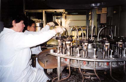
Assembling the tube
A typical glass audio tube is made on an assembly line by people wielding tweezers and small electric spot-welders. They assemble the plate, cathode, grids and other parts inside a set of mica or ceramic spacers, then crimp the whole assembly together. The electrical connections are then spot-welded to the tube's base wiring. This work has to be done in fairly clean conditions, although not as extreme as the "clean rooms" used to make semiconductors. Smocks and caps are worn, and each workstation is equipped with a constant source of filtered airflow to keep dust away from the tube parts.
Once the finished assembly is attached to the base, the glass envelope can be slid over the assembly and flame-sealed to the base disc. A small glass exhaust tube is still attached, and enters the envelope. The tube assembly is attached to a processing machine (sometimes called a "sealex" machine, an old American brandname for this kind of device). The exhaust tubing goes to a multistage high-vacuum pump. The sealex has a rotating turntable with several tubes, all undergoing a different step in the process. (See more pictures of glass tube assembly and production)
First comes vacuum pumping; while the pump runs, an RF induction coil is placed over the tube assembly and all the metal parts are heated. This helps remove stray gases trapped in the parts, and also activates the cathode coating.
After 30 minutes or more (depending on the tube type and the vacuum desir ed), the tube is automatically lifted up and a small flame seals its exhaust tubing.
The turntable rotates, and there may follow an electrical "break-in" period where the tube is put through a series of operational stresses, such as higher-than-rated heater voltages.
Then the tube is rotated to the getter-flash station, where a combination of RF induction heating and/or high-voltage discharge flashes the barium getter.
Finally the tube is removed, the base wiring is attached to the external base (if it is an octal base type) with a special heat-resistant cement, and the finished tube is ready for aging in a burn-in rack. If the tube meets a set of operational specs in a special tester, it is marked and shipped.
The getter
We want a good, hard vacuum inside a tube, or it will not work properly. And we want that vacuum to last as long as possible. Sometimes, very small leaks can appear in a tube envelope (often around the electrical connections in the bottom). Or, the tube may not have been fully "degassed" on the vacuum pump at the factory, so there may be some stray air inside. The "getter" is designed to remove some stray gas.
The getter in most glass tubes is a small cup or holder, containing a bit of a metal that reacts with oxygen strongly and absorbs it. (In most modern glass tubes, the getter metal is barium, which oxidizes VERY easily when it is pure.) When the tube is pumped out and sealed, the last step in processing is to "fire" the getter, producing a "getter flash" inside the tube envelope. That is the silvery patch you see on the inside of a glass tube. It is a guarantee that the tube has good vacuum. If the seal on the tube fails, the getter flash will turn white (because it turns into barium oxide).
There have been rumors that dark spots on getters indicate a tube which is used. This is NOT TRUE. Sometimes, the getter flash is not perfectly uniform, and a discolored or clear spot can occur. The tube is still good and will give full lifetime. THE ONLY RELIABLE WAY TO DETERMINE THE HEALTH OF A TUBE IS TO TEST IT ELECTRICALLY.
Glass power tubes often do not have flashed getters. Instead, they use a metal getter device, usually coated with zirconium or titanium which has been purified to allow oxidation. These getters work best when the tube is very hot, which is how such tubes are designed to be used. The Svetlana 812A and SV811 use such getters.
The most powerful glass tubes have graphite plates. Graphite is heat-resistant (in fact, it can operate with a dull red glow for a long time without failing). Graphite is not prone to secondary emission, as noted above. And, the hot graphite plate will tend to react with, and absorb, any free oxygen in the tube. The Svetlana SV572 series and 572B use graphite plates coated with purified titanium, a combination which gives excellent gettering action. A graphite plate is much more expensive to make than a metal plate of the same size, so it is only used when maximum power capability is needed. Large ceramic tubes use zirconium getters. Since you can't see a "flash" with such tubes, the state of the tube's vacuum has to be determined by electrical means (sometimes by metering the grid current).
By Eric Barbour
Information from www.vacuumtubes.net
The heater inside the cathode
An oxide-coated cathode can't heat itself, and it has to be hot to emit electrons. So, a wire filament heater is inserted within the cathode. This heater has to be coated with an electrical insulation that won't burn up at the high temperatures, so it is coated with powdered aluminum oxide. This is an occasional cause of failure in such tubes; the coating rubs off or cracks, so the heater can touch the cathode. This can prevent normal operation of the tube. And if the heater is running from AC power, it can put some of the AC signal into the amplifier's output, making it unusable in some applications. Good-quality tubes have very rugged and reliable heater coatings.
By Eric Barbour
Information from www.vacuumtubes.net
Audio Beam Tetrode
 This is a special kind of beam tetrode, with a pair of "beam plates" to constrain the electron beam to a narrow ribbon on either side of the cathode. Also, the control and screen grids have their wire turns aligned, much like the large ceramic tetrodes (above). Unlike the ceramic tetrodes, the grids are at a critical distance from the cathode, producing a "virtual cathode" effect. All this adds up to greater efficiency and lower distortion than a regular tetrode or pentode. The first popular beam tetrode was the RCA 6L6, introduced in 1936. Beam tetrodes still made today include the SV6L6GC and SV6550C; the former is most popular in guitar amplifiers, while the latter is the most common power tube in modern high-end audio amplifiers for the home. Today this design is seen only in glass tubes used in audio amplifiers, not in ceramic power tubes.
By Eric Barbour
Information from www.vacuumtubes.net
Other grids--the pentode
 By adding a third grid to the tetrode, we get a PENTODE. The third grid is called a suppressor grid and is inserted between the plate and the screen grid. It has very few wire turns, since its only job is to collect the stray secondary-emission electrons that bounce off the plate, and thereby eliminate the "tetrode kink". It is usually operated at the same voltage as the cathode. Tetrodes and pentodes tend to have higher distortion than triodes, unless special circuit designs are used (see ULTRALINEAR, below).
The EL34, EL84, SV83 and EF86 are true pentodes. The EL34 is widely used in guitar and high-end amplifiers as the power output tube. The smaller EL84 is seen in lower-cost guitar amps. The SV83 is used in a few high-end and guitar amps, while the EF86 is used as a low-noise preamp in guitar amps and professional audio equipment. One of the few large high-power pentodes is the 5CX1500B, often seen in radio transmitters.
There were tubes with more than three grids. The pentagrid converter tube, which had five grids, was widely used as the front-end frequency converter in radio receivers. Such tubes are no longer in production, having been fully replaced by semiconductors.
By Eric Barbour
Information from www.vacuumtubes.net
Screen grid--the tetrode
Adding another grid to a triode, between the control grid and the plate, makes it into a TETRODE. This "screen" grid helps screen,  or isolate, the control grid from the plate. This is important is reducing the so-called Miller effect, which makes the capacitance between the grid and plate look much bigger than it really is. The screen also causes an electron-accelerating effect, increasing the tube's gain dramatically. The screen grid in a power tube carries some current, which causes it to heat up. For this reason, screen grids are usually coated with graphite, to reduce secondary emission and help keep the control grid cool.
Many large radio and TV stations use giant metal-ceramic power tetrodes, which are capable of high efficiency when used as RF power amplifiers. Power tetrodes are also sometimes used in amateur radio and industrial applications. (Regular tetrodes are rarely used for audio applications because of an effect called "tetrode kink", caused by that secondary emission. Most of it is due to electrons bouncing off the plate, some from the screen.) This greatly increases distortion and can cause instability if not carefully dealt with in the design. See section F, "audio beam tetrodes", below.)
Large ceramic tetrodes are often called "radial beam tetrodes" or simply "beam tetrodes", because their electron emission forms a disc-shaped beam. The wires on their control and screen grids are aligned, a special trick which improves efficiency.
By Eric Barbour
Information from www.vacuumtubes.net
Control Grid
In nearly all glass audio tubes, the control grid is a p iece of plated wire, wound around two soft-metal posts. In small tubes the plating is usually gold, and there are two posts made of soft copper. Grids in big power tubes have to tolerate a lot of heat, so they are often made of tungsten or molybdenum wire welded into a basket form. Some large power tubes use basket-shaped grids made of graphite (see D below).
Inside any modern amplifying tube, one of the things to avoid is called secondary emission. This is caused by electrons striking a smooth metal surface. If many secondary electrons come out of the grid, it will lose control of the electron stream, so that the current "runs away", and the tube destroys itself. So, the grid is often plated with a metal that is less prone to secondary emission, such as gold. Special surface finishing is also used to help prevent secondary emission.
A tube with only one grid is a TRIODE. The most widely used small triode, the 12AX7, is a dual triode which has become the standard small-signal amplifier in guitar amps. Other small glass triodes used in audio equipment include the 6N1P, 6DJ8/6922, 12AT7, 12AU7, 6CG7, 12BH7, 6SN7 and 6SL7.
Many glass power triodes are currently on the market, most of them aimed at amateur radio or high-end audio use. Typical examples are the Svetlana SV300B, SV811/572 series, and 572B. Power triodes come in "low-mu" (low gain) and "high-mu" (high gain) versions. Low-mu triodes like the SV300B have very low distortion and are used in high-end audio amplifiers, while high-mu triodes are used mostly in radio transmitters and big high-power audio amplifiers.
Large ceramic-metal power triodes are often used in radio transmitters and to generate radio energy for industrial heating applications. Specialized triodes of many kinds are made for exotic applications, such as pulsed radars and high-energy physics work.
By Eric Barbour
Information from www.vacuumtubes.net
Plate (anode)
The plate, or anode, is the electrode that the output signal appears on. Because the plate has to accept the electron flow, it can get hot. Especially in power tubes. So it is specially designed to cool itself off, either by radiating heat through the glass envelope (if it's a glass tube), or by forced-air or liquid cooling (in bigger metal-ceramic tubes). Some tubes use a plate made of graphite, because it tolerates high temperatures and because it emits very few secondary electrons, which can overheat the tube's grid and cause failure. See "H--the getter" below for more about the graphite plate.
By Eric Barbour
Information from www.vacuumtubes.net
Cathode
Today, nearly all tubes use one of two different kinds of cathode to generate electrons.
1) The thoriated filament: it is just a tungsten filament, much like that in a light bulb, except that a tiny amount of the rare metal THORIUM was added to the tungsten. When the filament is heated white-hot (about 2400 degrees Celsius), the thorium moves to the outer surface of it and emits electrons. The filament with thorium is a much better maker of electrons than the plain tungsten filament by itself. Nearly all big power tubes used in radio transmitters use thoriated filaments, as do some glass tubes used in hi-fi amps. The thoriated filament can last a VERY long time, and is very resistant to high voltages.
2) The other kind of cathode is the oxide-coated cathode or filament. This can be either just a filament coated with a mixture of barium and strontium oxides and other substances, or it can be an "indirectly heated" cathode, which is just a nickel tube with a coating of these same oxides on its outer surface and a heating filament inside. The cathode (and oxide coating) is heated orange-hot, not as hot as the thoriated filament--about 1000 degrees Celsius. These oxides are even better at making electrons than the thoriated filament. Because the oxide cathode is so efficient, it is used in nearly all smaller glass tubes. It can be damaged by very high voltages and bombardment by stray oxygen ions in the tube, however, so it is rarely used in really big power tubes.
3) Lifetime of cathodes: The lifetime of a tube is determined by the lifetime of its cathode emission. And the life of the of a cathode is dependent on the cathode temperature, the degree of vacuum in the tube, and purity of the materials in the cathode.
Tube life is sharply dependent on temperature, which means that it is dependent on filament or heater operating voltage. Operate the heater/filament too hot, and the tube will give a shortened life. Operate it too cool and life may be shortened (especially in thoriated filaments, which depend on replenishment of thorium by diffusion from within the filament wire). A few researchers have observed that the lifetime of an oxide-cathode tube can be greatly increased by operating its heater at 20% below the rated voltage. This USUALLY has very little effect on the cathode's electron emission, and might be worth experimenting with if the user wishes to increase the lifetime of a small-signal tube. (Low heater voltage is NOT recommended for power tubes, as the tube may not give the rated power output.) Operating the heater at a very low voltage has been observed to linearize some tube types-- we have not been able to verify this, so it may be another worthy experiment for an OEM or sophisticated experimenter. The average end-user is advised to use the rated heater or filament voltage--experimentation is not recommended unless the user is an experienced technician.
Oxide cathodes tend to give shorter lifetimes than thoriated filaments. Purity of materials is a big issue in making long-lived oxide cathodes--some impurities, such as silicates in the nickel tube, will cause the cathode to lose emission prematurely and "wear out". Low-cost tubes of inferior quality often wear out faster than better-quality tubes of the same type, due to impure cathodes.
Small-signal tubes almost always use oxide cathodes. Good-quality tubes of this type, if operated well within their ratings and at the correct heater voltage, can last 100,000 hours or more.
The world record for lifetime of a power tube is held by a large transmitting tetrode with a thoriated filament. It was in service in a Los Angeles radio station's transmitter for 10 years, for a total of more than 80,000 hours. When finally taken out of service, it was still functioning adequately. (The station saved it as a spare.) By comparison, a typical oxide-cathode glass power tube, such as an EL34, will last about 1500-2000 hours; and a tube with an oxide-coated filament, such as an SV300B, will last about 4000-10,000 hours. This is dependent on all the factors listed above, so different customers will observe different lifetimes.
By Eric Barbour
Information from www.vacuumtubes.net
INSIDE A TUBE
All modern vacuum tubes are based on the concept of the Audion- -a heated "cathode" boils off electrons into a vacuum; they pass through a grid (or many grids), which control the electron current; the electrons then strike the anode (plate) and are absorbed. By designing the cathode, grid(s) and plate properly, the tube will make a small AC signal voltage into a larger AC voltage, thus amplifying it. (By comparison, today's transistor makes use of electric fields in a crystal which has been specially processed--a much less obvious kind of amplifier, though much more important in today's world.)
Figure 3 (Inside a miniature tube) shows a typical modern vacuum tube. It is a glass bulb with wires passing through its bottom, and connecting to the various electrodes inside. Before the bulb is sealed, a powerful vacuum pump sucks all the air and gases out. This requires special pumps which can make very "hard" vacuums. To make a good tube, the pump must make a vacuum with no more than a millionth of the air pressure at sea level (one microTorr, in official technical jargon). The "harder" the vacuum, the better the tube will work and the longer it will last. Making an extremely hard vacuum in a tube is a lengthy process, so most modern tubes compromise at a level of vacuum that is adequate for the tube's application.
First, let's talk about the parts of the tube.........
The BASICS
Back in 1904, British scientist John Ambrose Fleming first showed his device to convert  an alternating current signal into direct current. The "Fleming diode" was based on an effect that Thomas Edison had first discovered in 1880, and had not put to useful work at the time. This diode essentially consisted of an incandescent light bulb with an extra electrode inside. When the bulb's filament is heated white-hot, electrons are boiled off its surface and into the vacuum inside the bulb. If the extra electrode (also called an "plate" or "anode") is made more positive than the hot filament, a direct current flows through the vacuum. And since the extra electrode is cold and the filament is hot, this current can only flow from the filament to the electrode, not the other way. So, AC signals can be converted into DC. Fleming's diode was first used as a sensitive detector of the weak signals produced by the new wireless telegraph. Later (and to this day), the diode vacuum tube was used to convert AC into DC in power supplies for electronic equipment.
Many other inventors tried to improve the Fleming diode, most without success. The only one who succeeded was New York inventor Lee de Forest. In 1907 he patented a bulb with the same contents as the Fleming diode, except for an added electrode. This "grid" was a bent wire between the plate and filament. de Forest discovered that if he applied the signal from the wireless-telegraph antenna to the grid instead of the filament, he could obtain a much more sensitive detector of the signal. In fact, the grid was changing ("modulating") the current flowing from the filament to the plate. This device, the Audion, was the first successful electronic amplifier. It was the genesis of today's huge electronics industry.
Between 1907 and the 1960s, a staggering array of different tube families was developed, most derived from de Forest's invention. With a very few exceptions, most of  the tube types in use today were developed in the 1950s or 1960s. One obvious exception is the 300B triode, which was first introduced by Western Electric in 1935. Svetlana's SV300B version, plus many other brands, continue to be very popular with audiophiles around the world. Various tubes were developed for radio, television, RF power, radar, computers, and specialized applications. The vast majority of these tubes have been replaced by semiconductors, leaving only a few types in regular manufacture and use. Before we discuss these remaining applications, let's talk about the structure of modern tubes.
By Eric Barbour
Information from www.vacuumtubes.net
